25 November 2021
Next article: Hard-wiring an LNB to use the high band 10.6 GHz oscillator
In this post I will present how it is possible to receive beacon signals from the Starlink satellites in low-Earth orbit using ordinary hardware that you most likely already have laying around or that is widely available.
Things you will need:
A few days ago, Oleg Kutkov (who I’ve met at the Starlink subreddit discussing exactly this before Starlink was even operational) announced in a tweet that he’s finally been able to detect beacon emissions from the Starlink satellites. I have been on the lookout for these signals as well, so I quickly checked to see whether the satellites are also active above my location (central Europe), and indeed I immediately spotted strong clusters of carrier waves around 11325 MHz with the unmistakable Doppler shift that only a quick-moving satellite in low-Earth orbit can produce. This came as a surprise as I personally wasn’t expecting any narrowband emissions from the satellites, but it does make sense that a beacon like this would be very useful for precise orbit determination (and possibly help SpaceX with orbit management and collision avoidance?).
While my first course of action was to mount an LNB on the biggest dish reflector I own, I soon noticed that the beacons have a very high signal-to-noise ratio and realized that it may be possible to receive them with a fixed antenna with a much wider beam than a dish (and without the need to actively track the satellites). Building such antenna for the Ku-Band would have been very difficult, but luckily it is possible to just use an LNB alone without a dish pointed directly up.
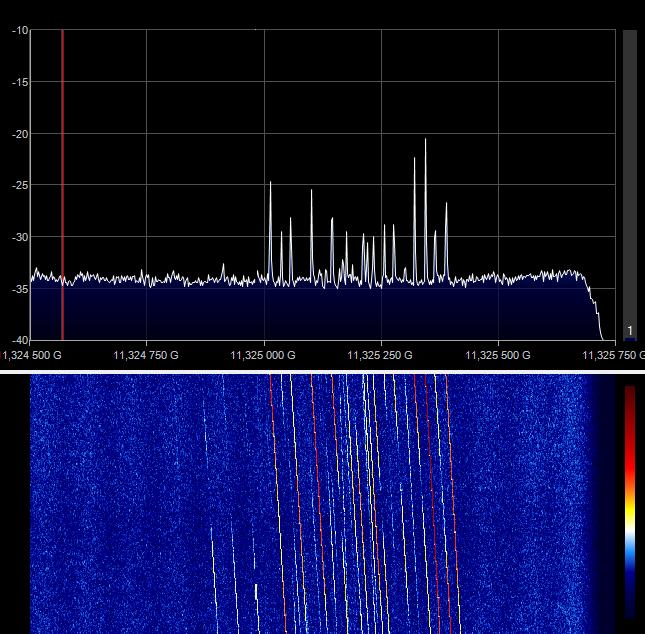
And behold; the signals coming through just an old LNB sitting on a table had more than enough strength to be noticeable and audible, with the wider beam of the LNB allowing the reception of multiple satellites simultaneously (I believe at one point I was able to see distinct Doppler curves from four or five satellites at once).
The above image shows an FFT screenshot of the eacon signals from multiple Starlink satellites being received by an old LNB sitting on a table. Afterwards I have decided to put the LNB into a location where it has a better view of the sky. The best spot I could find on the balcony was a leftover scaffolding pipe, so I temporarily taped it to the pipe with a bent copper wire for some separation, creating what probably was and still is the worst Starlink antenna ever devised.
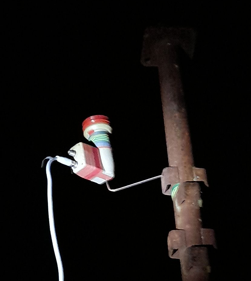
Despite its questionable appearance it worked surprisingly well. After connecting my SDR and powering it up, I left it running for several minutes, rendering a slow waterfall plot in SDR#;
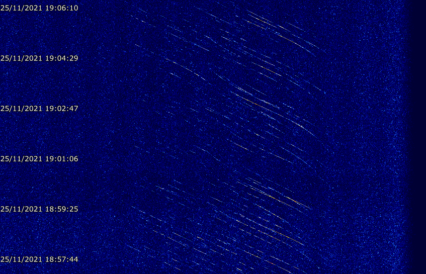
Even though the LNB has a much wider beam width than a dish reflector, it still isn’t able to receive the beacon for most of the satellite’s pass. I have also noticed that the signals tend to get a lot weaker when receiving at an angle, suggesting the satellite’s own antenna array is beamed narrowly, so an antenna with a beam wider than the LNB would probably be detrimental to the setup.
But even despite all of that, in the roughly 30 minutes of receiving there was hardly any time where a Starlink satellite wasn’t inside the LNB’s field of view. This is both impressive and slightly disturbing, but that is a discussion for another time and place.
To power the LNB I am using a DIY control box that allows me to switch the supply voltage (polarization) and control signal (LO frequency) going to the LNB. Luckily this isn’t needed at all, instead just a simple coaxial cable power injector (bias-t) can be used to supply the LNB with 12-18 volts DC. These are very cheap as they are widely used in terrestrial TV reception.
Make sure to never connect a power injector or a Bias-T backwards; sending direct current into an SDR can destroy it. Use an additional DC blocker on the input of your SDR if you want to be extra safe, or at the very least check whatever you are connecting to your SDR with a voltmeter beforehand to make sure no current will be passed where it shouldn’t. I made this mistake several times already, and it's only been pure luck that it hasn't resulted in the death of my SDR.
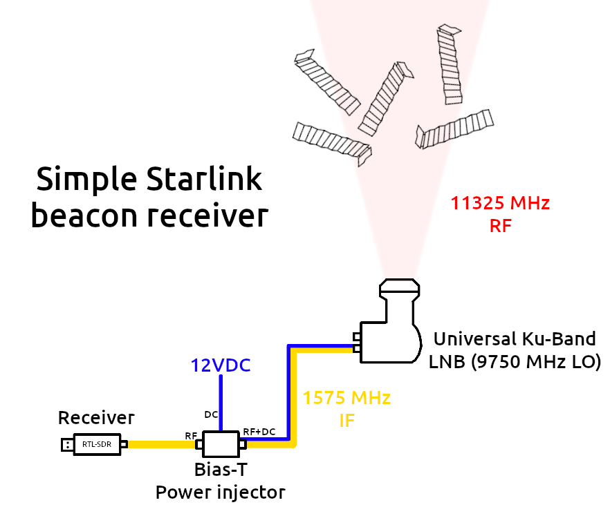
As mentioned briefly above, pretty much any Ku-Band LNB can be used. The absolutely most used standard - at least in Europe - is the universal linear “Astra” LNB which has LO frequencies of 9.75 and 10.6 GHz. The Starlink beacons can be received with the 9.75 GHz LO which also happens to be the default, hence why you don’t need any other control hardware besides the power injector.
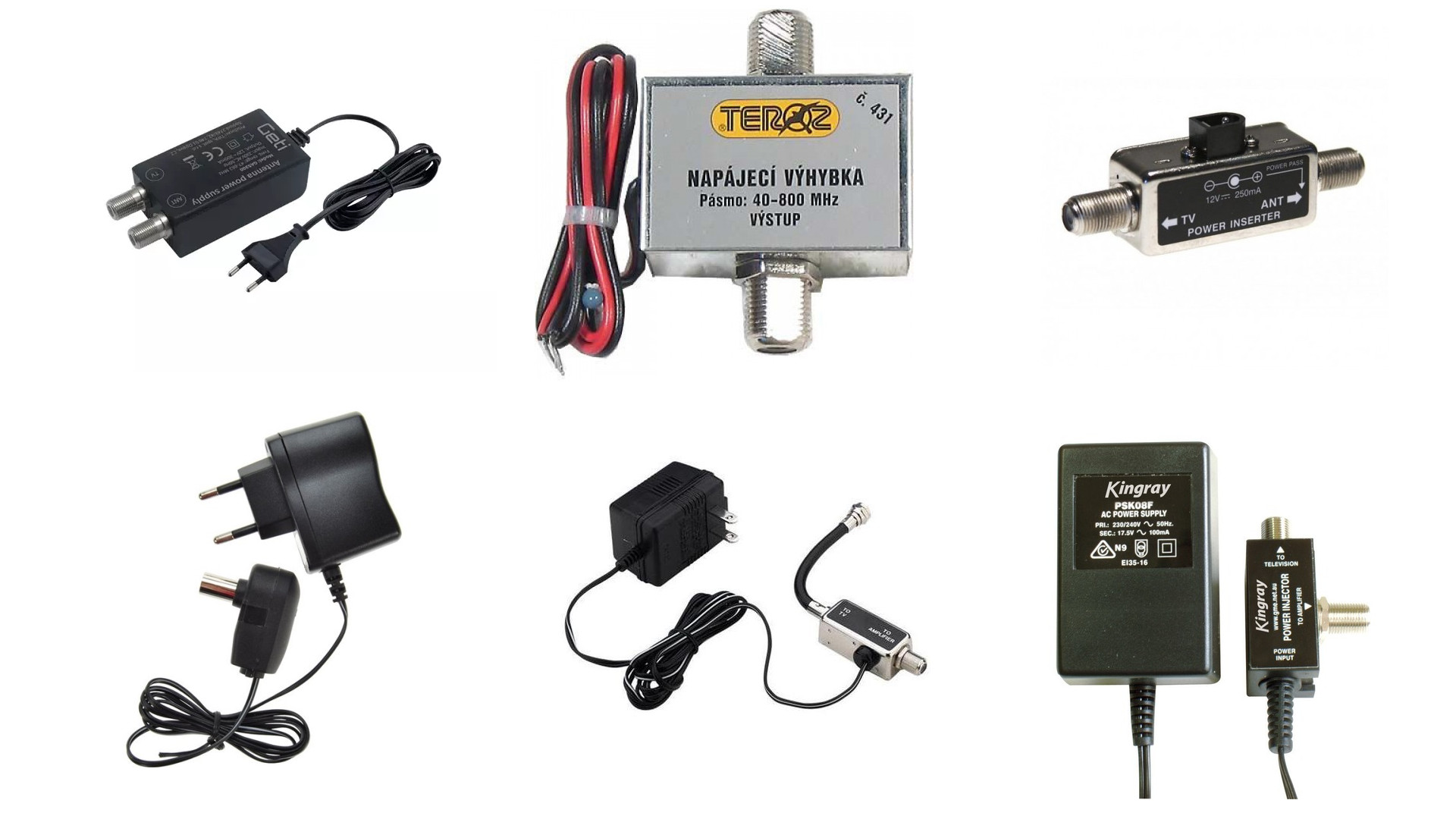
Examples of power injectors. The best ones for this case would be the ones with F connectors. If you want to use an injector with its own power supply, make sure it is DC and within the 12-18 volt range. If it’s not then you can chop it off and connect your own voltage source to the exposed wires. (Also don’t worry about the frequency range being lower than the LNB IF output, it’s going to be fine as long as you aren’t using a specifically filtered injector)
The LNB mixes the 11325 MHz Starlink signal with whatever the frequency of its LO is. We can calculate the output (IF - intermediate frequency) by subtracting the LO frequency from the input. In case of the standard 9.75 GHz LNB it is
11325 - 9750 = 1575
So the frequency the SDR actually tunes to is 1575 MHz, which is well within the range of most SDRs. If you do use an LNB with a slightly different LO, simply redo the calculation. Also note that pretty much no stock TV LNBs have their LO frequency exactly as specified, so don’t be surprised if you see the Starlink signal a few dozen kHz up to a MHz off (depending on the age and internal construction of your LNB, you might have to look a few MHz around).
Some software like SDR# allows you to input a converter LO and it will automatically recalculate the tuning frequency. That is why on the signal screenshots in this post you see the true RF frequency, even though my SDR (Airspy Mini) was tuned to 1575 MHz.
According to a quick Google search, the Starlink satellites use both RHC and LHC polarizations to communicate with the ground. The reason a standard cheap linear V/H LNB such as the one I used can still receive the circular signals is that the mismatch loss between the two is in theory around 3dB. While this would probably hurt the signal integrity a lot in case of the actual internet broadcast, we are working with a comparatively extremely narrow, extremely power-dense beacon, which results in the lin/circ polarization mismatch loss being negligible (it’s like looking at the Sun with sunglasses; even though its dimmer you can still clearly see it and potentially hurt your eyesight so don’t do that).
One fun thing about the Starlink beacons is that each satellite broadcasts a cluster of many carriers. This allows you to select a frequency somewhere in the middle of the cluster and listen to the Doppler shift using single-sideband audio demod (USB/LSB/DSB), nicely illustrating the effects of Doppler shift on radio signals as the individual signals pass by your tuner frequency. The shift is also enhanced by the very high orbital speed of Starlink and the high frequency used. This is the exact same principle that traffic radars use to measure your speed, except instead of your car transmitting a beacon the radar bounces its own signal off it. In fact, some Doppler radars work in the exact same frequency range, for example the cheap HB100 radar module which is tuned to 10525 MHz by default.
Whatever you decide to do with the signal, whether it’s Doppler analysis using software like strf or simply just listening to it for a while and showing it off to people, I hope this post was helpful and cleared things up. This is a unique opportunity to experiment with a whole different frequency band and hardware for SDR owners without having to spend obscene amounts of money on precision, custom, or obscure RF hardware and expensive SDRs.
If you have any questions or suggestions, feel free to contact me through my social media. Thanks for reading!
Next article: Hard-wiring an LNB to use the high band 10.6 GHz oscillator