2 December 2021
Previous article: Receiving Starlink satellite beacons on a budget
In this post I will show how I modified an old DRO universal Ku-Band LNB to use the “high band” 10.6 GHz local oscillator without the need of any additional control circuitry besides a power injector (bias-tee). This is a loose continuation of my previous blog post in which I’ve outlined how an LNB just like this can be used to receive radio beacons from the Starlink satellites.
I have shown that after connecting an LNB to an SDR and powering it up, very strong beacon emissions can be received from the satellites at 11325 MHz, which translates to 1575 MHz IF. This is the “intermediate frequency” - a product that is created by mixing the signal received by the LNB with a signal from its built-in local oscillator.
It was possible to use an unmodified LNB to receive the beacons because when no control circuitry is used and the LNB doesn’t receive a command to switch to the high band oscillator, it uses the “low band” 9.75 GHz oscillator by default. Knowing the oscillator frequency, we can arrive at the already mentioned IF frequency, by subtracting the LO from the RF; 11325 - 9750 = 1575.
By reversing that simple equation, we can come up with what the actual RF range is of a receiver such as the RTL-SDR V3 when connected to such LNB. Let’s assume the operational range of the SDR is 20 - 1750 MHz. We can add the local oscillator frequency of the LNB to arrive at a new range of 9770* - 11500 MHz. As noted, the Starlink beacon frequency was within this range, so the SDR can receive it.
* the actual range will be a few hundred MHz narrower as the LNBs often filter out output IF frequencies below around 800 MHz, or they don’t amplify them fully resulting in significantly worse performance when tuning there
However, after I released that post it came to light that there are at least three other beacon frequencies, at 11575, 11950 and 12450 MHz respectively. It also turns out the four known beacon frequencies don’t contain identical traffic, with the 11950 MHz beacons specifically appearing to be consistently the most active and strongest, making them the most desirable frequency to receive. But as specified above, even the extended range of an RTL-SDR won’t cover this frequency, meaning that a higher value local oscillator is required.
![]()
Luckily, the exact same universal Ku-Band LNBs also contain a second “high band” oscillator which nominally resonates at 10600 MHz. Normally it is the TV receiver that commands the LNB to switch between its two oscillators based on what channel is selected, but another way has to be found if we want the high band to be active while an SDR is connected.
Because the LNB is usually only connected to the TV receiver with a coaxial cable, there isn’t a serial or a parallel bus through which proper digital communication can take place. Instead, when the receiver wants to tell the LNB that it should switch to the high band, alongside the direct current it normally sends up the coax it also injects a 22 kHz control signal. This frequency is close enough to DC (relative to the hundreds of MHz that the LNB IF section operates at) that it gets filtered out and separated by the same circuitry as DC inside the LNB while also being far enough from DC that the LNB can detect its presence alongside it.
This results in simple 1/0 communication that the LNB uses to pick the oscillator. When the signal is detected, the high band is used. When the signal isn’t detected, the LNB defaults to the low band, with the latter case being what I’ve used for the 11325 MHz Starlink beacons.
Let’s counterintuitively talk about a method other than the one the rest of the post will be focusing at, just to give you the idea of how it could be done without opening up the LNB and hard-wiring it.
Probably the most neat and SDR-friendly way to switch to the high band of an LNB is to use an in-line 22 kHz signal generator. I bought one that I integrated into my LNB controller - it runs on the same voltage as the LNB and both uses and passes bias-tee current, making it a drop-in solution which then simplifies the high band selection into just a switch flip. Of course this isn’t a viable option for everyone and all use cases. It costs money and may not even be available for purchase in some countries. And even though I own it, I still wouldn’t want to sacrifice it into a permanent setup, such as a dedicated LNB for Starlink beacon “monitoring”. There, hard-wiring the LNB is still better as it will not require this generator (and by extension consume less electric current and reduce failure points).
When a pre-built signal generator isn’t available, it is possible to design and build one on your own, which however is something I will not be focusing on as I haven’t done that (yet), though I will provide you with a photo of the very simple circuitry that the pre-built generator is using, based on a single 555 IC, should you decide to attempt constructing one on your own;
But now, let’s finally get to the main topic!
The most important characteristic of an LNB that will dictate how this modification is done is what method the LNB uses to synthesize the LO frequency. You may already be familiar with these terms if you’ve ever shopped for an LNB for satellite television. Most modern LNBs use a phase-locked loop (PLL), while the older ones use dielectric resonator oscillators (DRO). In the first example I am using an old Grundig DRO LNB, which generally will have a much simpler construction (there will be many more parts than in a PLL LNB, however it will be much clearer to see how the LNB functions and selects the LO frequency).
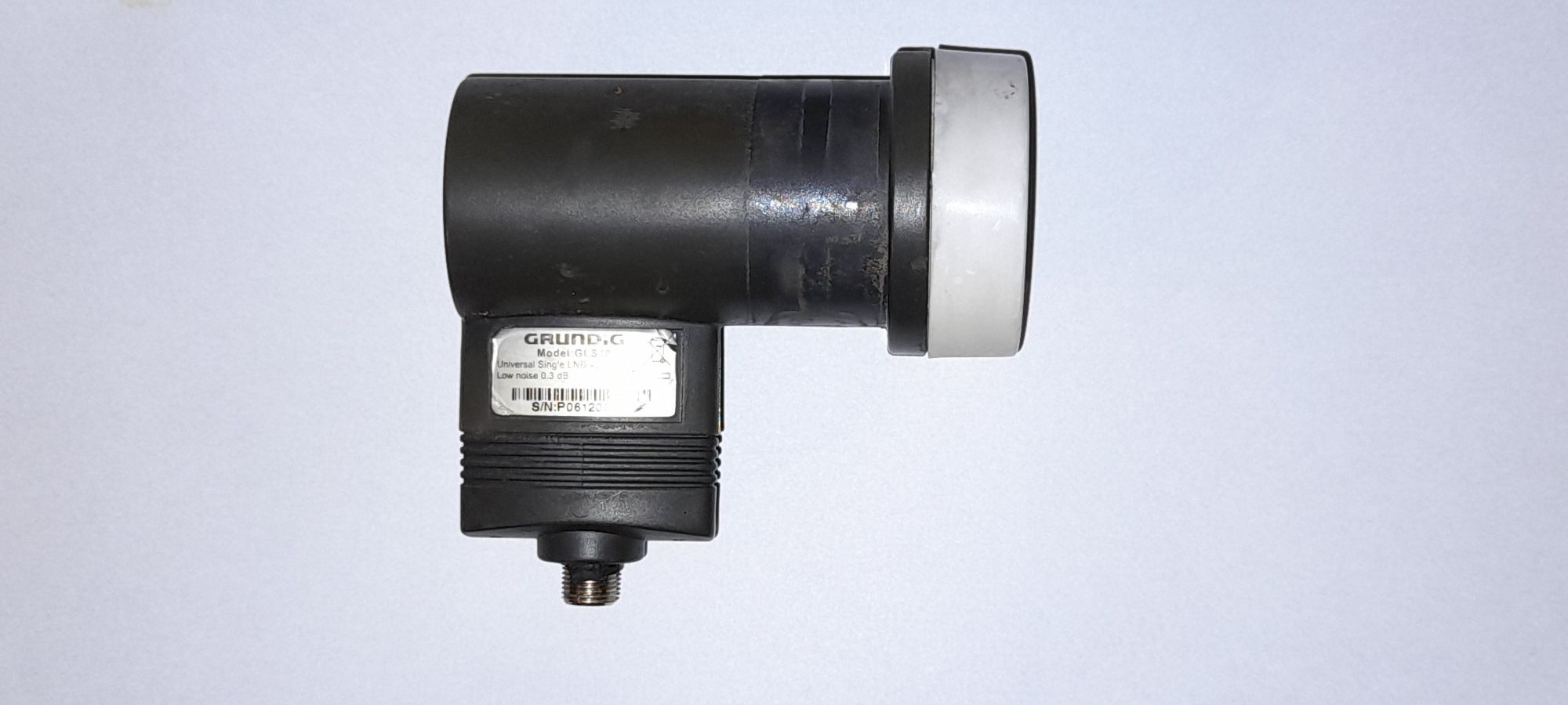
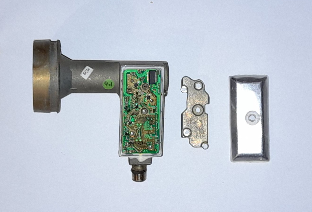
The first step is disassembling the LNB. The plastic shell consists of four parts; The two halves that go around the LNB, the waveguide cover, and a rain cover around the F connector. In this case they are held together by small tabs, so with some care it was possible to take them apart without too much damage, revealing the actual metal body of the convertor (and the spider nests that built up inside while the LNB was in use, cleared out in the following picture).
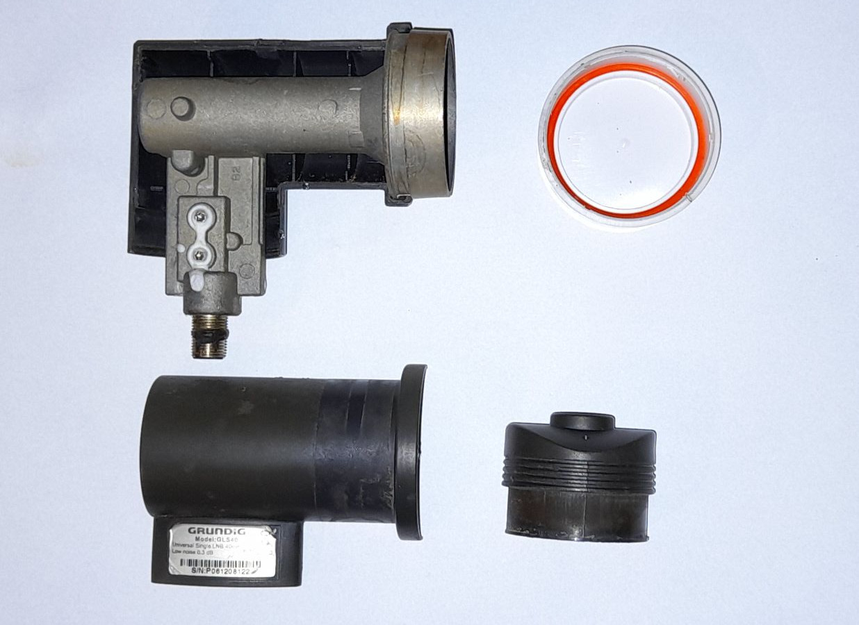
After the plastic cover is off, the first part of the metal cover can be taken off as well. This is usually held down with a combination of screws and some sealant/glue (often also applied on top of the screws) that need to be located first.
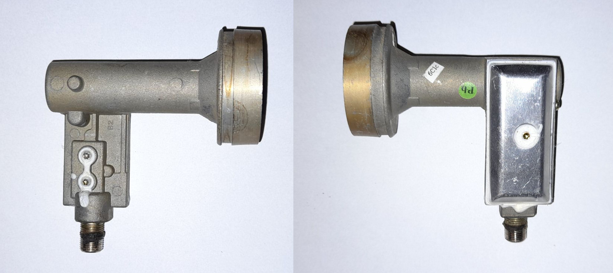
The above image shows the bare LNB from both sides. You can see four Torx/six-lobe screws in total, on the image on the left there are two screws right above the F connector, and on the image on the right there is one in the middle of the metal cover and one at the back side of the LNB, right next to the bottom of the waveguide. It is important to not unscrew what isn’t necessary. In the case of this LNB, the outer metal cover is only held by the single screw in its center, so only that one should be taken out. The screw at the back side of the LNB plays no role in holding down the cover or the inside RF shield so it can be left in, and the two screws at the other side (pictured left) aren’t used to hold down anything, instead they are the tuning screws of the two DROs, so you shouldn’t touch those at all (for now). You can usually identify the tuning screws since they will be in a pair, often located in a specifically shaped part of the metal cast and encased in sealant. These are used for slight adjustments of the frequency of each oscillator, which will come into play at a later point.
Once all the (one) screws are removed from the metal cover, it can be gently pried open. I used a small flat screwdriver, you can also use a small knife that will help with removing the sealant on the edges of the cover. Be very careful when stabbing anything below the cover, as that is where the actual PCB lives and you don’t want to damage it.
Taking off the outer metal cover also reveals an additional inner RF shield, which in this case was held down by four more screws. In the case of this LNB, the DROs are located on the bottom side of the board (not visible here), however you may encounter an LNB that has the DROs on the same side as the traces and also has the tuning screws on the inner RF shield instead of the outer metal cast like this one. If that is the case, once again, try not to disturb the tuning screws while taking off the RF shield.
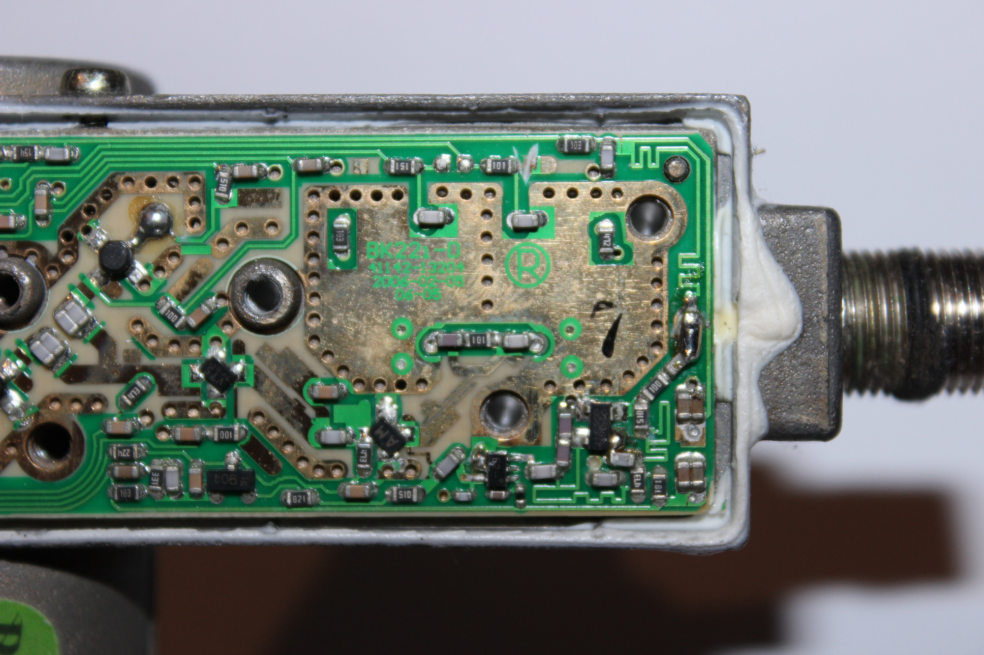
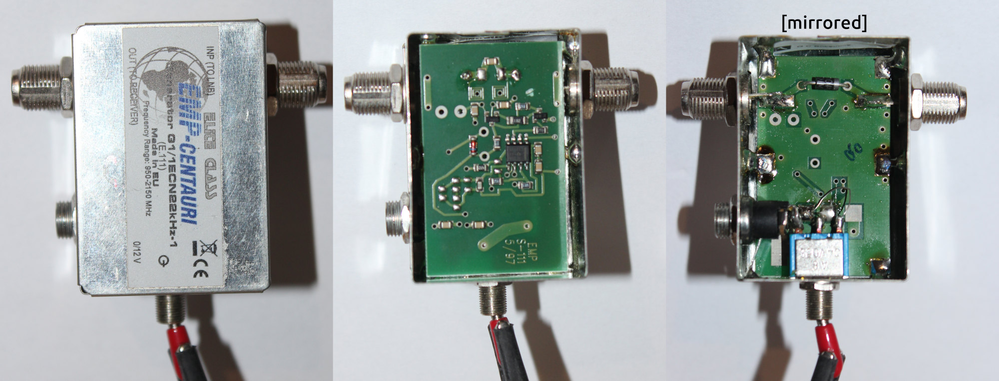
Once you have access to the PCB, you will need to locate the circuitry responsible for switching the LO. In this case I noticed a pair of traces going from the integrated circuit to the other side of the PCB with a capacitor, and then re-emerging as RF traces going into a printed filter, which was a dead giveaway of how this LNB switches the oscillators. I used a multimeter to confirm, and indeed once the LNB is switched on, the IC applies voltage to one of the traces while grounding the other one. This was already enough info to tell me which trace is powering the low (right) and which the high band (left) LO. Thus my goal was to re-route the voltage from the input of the right resistor to the left one, which I did using the following modifications;
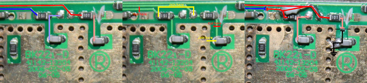
First I cut the trace that the IC would normally use to power the high band LO so that the rerouted current wouldn’t short to ground through the IC and kill it. Then I also cut the trace going into the low band LO, followed by shorting it to ground using a blob of solder, effectively disabling it permanently. The short to ground may not be important, however when it comes to microwave electronics the last thing I would want on the PCB was a floating trace. The last (and most difficult) task was to solder in a tiny piece of wire that routes the current from the IC into the resistor of the high band LO. I noticed that each resistor has a different value (probably for the different current/voltage requirement of each LO), so I wanted to use the high band LO’s original resistor.
Ideally you would use a solid core insulated wire, such as what is used in Ethernet cables, and definitely not what I used in this example. Thin solid core wire will also be easier to shape in its place, which is important because once the metal covers are put back there is very little space available. Following is another photo of the board after my modification, without the annotations. Note that I also put a piece of electrical tape over the wire afterwards to make sure it wouldn’t contact the RF shield or the metal cover once assembled.
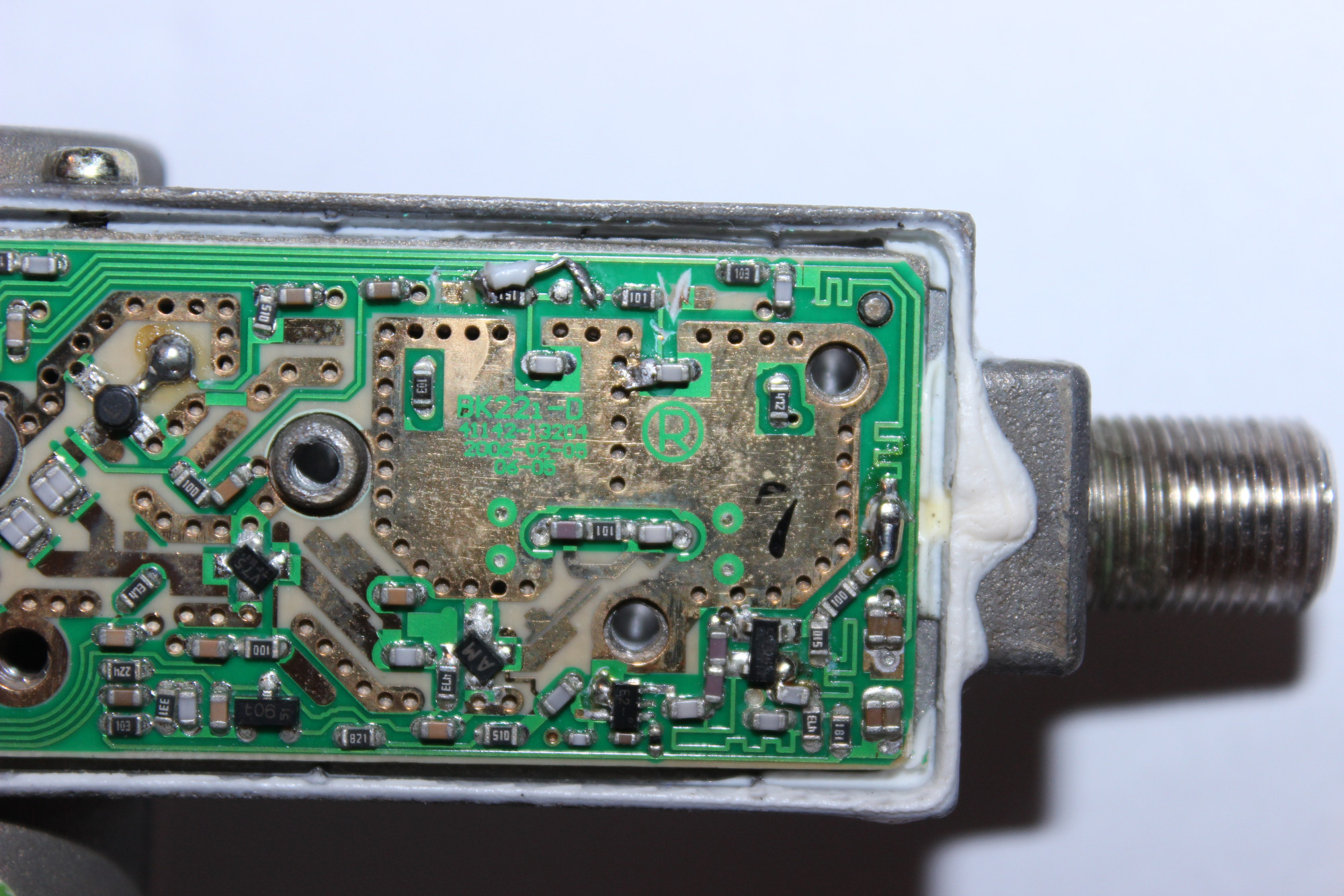
Before closing the LNB back up I used a multimeter in the continuity test mode to make sure the cut traces really were cut and the joined traces really were joined. I also powered up the LNB again for a short time and made sure there is now voltage being applied to the high band LO by default while the low band LO is held at 0 volts ground. If you do decide to do this, try to keep the LNB powered on for as little time as possible while the metal covers are taken off, especially if your DROs are exposed. Make sure there is no obstruction in front of the waveguide and no objects near any of the RF traces (besides the multimeter probes).
Once I was confident that the current was going where it was supposed to, I closed the LNB back up, and it was ready for its first test. I put it outside the window aimed roughly up and powered it up. The noise floor increased as expected, however I couldn’t actually see any of the Starlink beacons. Why was that?
Remember the tuning screws, and how I talked about not disturbing them? Well I disturbed them by taking them completely out and then putting them back in after I realized it wasn’t needed. Since I didn’t screw them back in precisely into their original position, the high band LO ended up being detuned. Luckily this doesn’t really matter, as long as you can actually identify what the new LO frequency is (and as long as the DRO wasn’t physically damaged by the screw). I did that simply by clicking through the spectrum in 1 MHz steps until I detected the Starlink beacons around 1270 MHz IF. To be certain these were the 11950 MHz beacons, I tuned 375 MHz lower where the 11575 MHz beacons live, and indeed after a while I detected Starlink emissions there as well. I then used the above mentioned IF formula in reverse to work out the LO, since I knew both the IF and RF;
If you are more careful than me, hopefully you won’t have to hunt down the beacons afterwards and your LO will only be a few hundred kHz or just a couple MHz off. While I kept my LO slightly higher than the default, I will just refer to it as 10600 MHz for the purposes of this post as that is what you will most likely end up with.
Armed with the 10600 MHz LO, when the LNB is used with something like an RTL-SDR V3, its receive range will effectively be shifted from 20 - 1750 MHz MHz to 10620 - 12350 MHz, which is enough to receive three out of the four Starlink beacon frequencies, including the most active one at 11950 MHz. Following is one additional example, this time using a defunct circuit board of a modern, brand new, dirt cheap PLL LNB.
Modern PLL LNBs can be this cheap because everything about them has been optimized and made as simple to manufacture as possible. This means that the majority of the components you’ve seen in the previous DRO example are now contained within a single integrated circuit. Sadly I won’t be able to actually do the mod with this LNB and test it, as it’s already been abused a lot and isn’t working anymore, but the (mostly) intact PCB is enough to demonstrate how you would go about modifying it (your LNB will most likely be different, so having a second complete real-world example wouldn’t help much anyway).
Getting to the circuit board is the exact same process as before, except this particular LNB had to have its plastic shell taken off destructively as it wasn’t made to be disassembled (for obvious reasons). If you have an LNB like that, try to preserve as much of the shell as possible so you can at least tape or glue it back if you want.
The first step once the PCB is exposed is locating the switching circuitry, just like before. This will be a bit more difficult as PLL LNBs don’t use two discrete oscillators but instead just a single low-frequency crystal reference that is then used to synthesize the LO frequency inside the chip by variable frequency multipliers. This means that if all of the switching is done completely on-chip then there won’t be a way to modify the LNB to use the high band by default. But before coming to this conclusion, let’s see the circuit board in question;
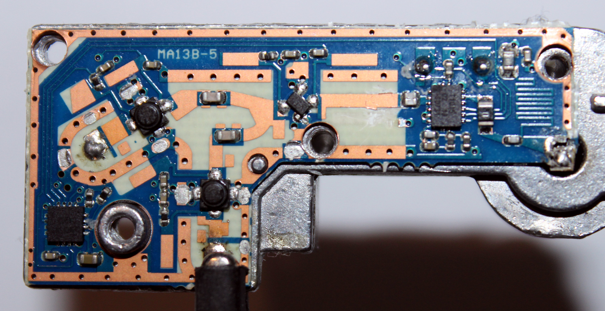
We can see that the bulk of the circuitry consists of two ICs and three amplifiers. The two amplifiers are feeding into the third one through capacitors, with the output of the final amplifier going through another pair of capacitors directly into one of the ICs. This is the chip that is responsible for the LO synthetization and mixing, something that a DRO LNB needs an entire section of the board dedicated for. Another trace then carries the resulting IF through a zero ohm resistor (acting as a bridge in this case) and another capacitor directly into the center pin of the F connector.
The first thing you should do when you encounter chips like this is to look up their datasheets. There’s about a 50/50 chance that it won’t exist, but if it does then it will show you exactly what you need to do in order to modify the LNB. In my case, the PLL/mixer chip is marked “T1015” while the other accompanying chip is marked “04202”. While I could not find any info about the latter, I did manage to find a complete datasheet of the PLL chip here (alternate link).
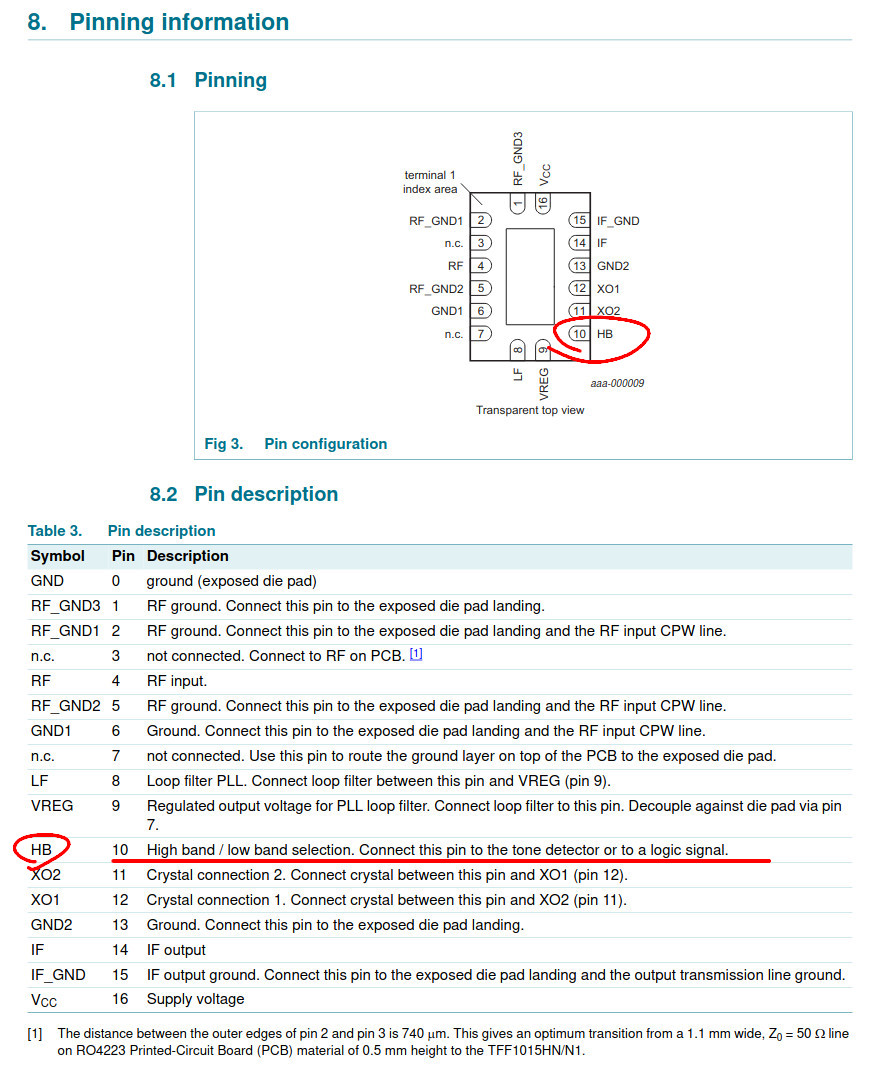
All I had to do was scroll down to the pin description, and indeed, very conveniently, the chip has a dedicated “HB” pin with an internal pull-down resistor. Unfortunately the datasheet doesn’t specify whether the high band is selected by setting the pin high or low, and I can’t power up this PCB to check either, however for the purposes of this example I will just assume that by default this pin is held low and the high band is selected only when voltage is applied to it, specifically 2.0 - 5.5V as specified by the “high level input voltage on pin HB” in the datasheet. Since this logic voltage is the same as the chip’s supply voltage, to permanently enable the high band it is only needed to short this pin to Vcc. I would also probably cut the existing trace going to the HB pin; just like with the DRO LNB, this trace is held at ground by default, so shorting it with a powered trace could cause issues and current going to places where it doesn’t belong.
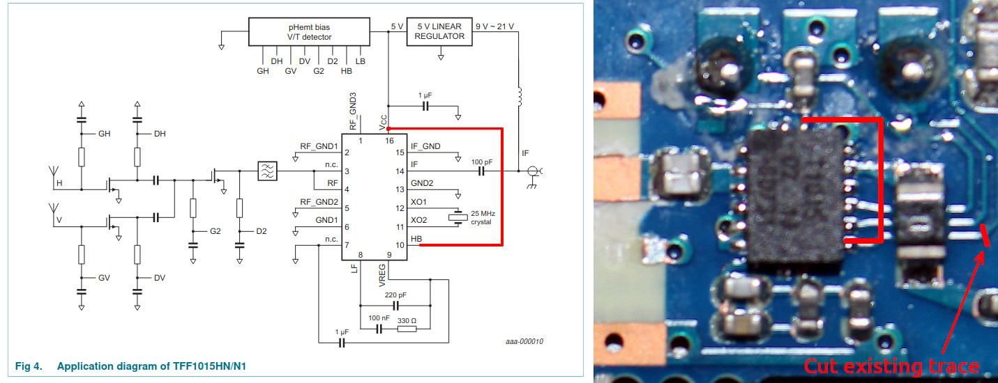
This sounds easier than it’s done though. Even if the modification itself is very simple, there is still the challenge of locating good places to solder a jumper wire to without disturbing any of the RF components, while also being small enough to fit back under the cramped RF shield. I would probably try to use thin coated transformer wire and join the HB pin on the chip to the bottom of the capacitor right above the chip, as that (according to the datasheet) should be connected to Vcc as well. However I can’t afford the soldering tools necessary to perform this modification without destroying the PCB and chip in the process, so unlike with the previous example I sadly won’t be able to include a photo of a modified board. Unfortunately I think that this would also be the case with many other people, so even though this LNB could in theory be modified significantly easier than the previous one, in practice it isn’t very doable without precision tools.
It does however serve as a good example of the differences between modifying a DRO and PLL LNB to use the high band without a 22 kHz control signal.
While hard-wiring an LNB like this isn’t the easiest task, assuming that you can get an LNB that you don’t mind losing, you do end up with a device that easily extends the range of your SDR receiver beyond what’s possible with just a normal LNB and no control signal. Of course the LNB can be mounted into the focal point of a dish reflector and used to receive signals from other satellites, such as the many strong telemetry beacons from geostationary satellites, that - unlike Starlink’s - do actually contain some data. This is something that I’ve been trying to write about for a while now but never found the motivation to finish, so do expect that in the (not so) near future.
Even if admittedly there aren’t that many interesting signals to receive with either a modded or a stock Ku-Band LNB, I think that doing a simple modification like this can also serve as basic introduction to how LNBs work and are designed, with the general understanding of the PCB layout then enabling you to come up with your own modifications that could be done.
One for example is shifting the LO frequency of the LNB higher or lower, which again is something I plan writing about as combined with the permanent high band mod it can be used to receive the final fourth 12450 MHz beacon frequency (that falls just short of the 1750 MHz limit of an RTL-SDR even with the high band mod, being at 1850 MHz IF).
Like before, I thank you for reading and hope that you’ve learned something or at least found the article interesting. Once again if you have any questions or suggestions, feel free to contact me using any social media.
Previous article: Receiving Starlink satellite beacons on a budget