
17 December 2021
⇈ Table of contents
↓ 1.1 Below 1.7 GHz
⇊ 2. Hardware Requirements
In this blog post I will try to explain what HRPT is and how to receive it using a cheap hardware setup based on an RTL-SDR. I will try my best to present the information in such a way that you should be able to understand it even with limited knowledge and experience with receiving satellites, however some basic knowledge of SDR and how to operate it will be necessary, otherwise the topic would get way too convoluted. Still it is very likely you will come across sections with information you already know, so I will provide a link to skip each section. I will also update this post when needed. When that happens, I will add a note with a section link directly below this paragraph so you can only read the updated parts in the future.
13 November 2022 - updated general info to represent changes to HRPT since publishing
⇈ Table of contents
↓ 1.2 What is HRPT
It is pretty much impossible to talk about HRPT without at least mentioning APT and LRPT. If you've had any exposure to or experience with SDR and satellites before, that is most likely one of the things you've heard about or possibly even tried receiving yourself.
It is easy, only requires a cheap SDR usually without any additional amplifiers or filters, and a very satisfactory omni-directional antenna can be as simple as two wires at an angle. It is what the majority of amateur weather satellite reception consists of to this day, and for good reasons.
However, because APT and LRPT broadcasts take place in the 137 MHz range, they are subject to severe limitations when it comes to data throughput, bandwidth, and in many cases also very strong interference from digital aircraft data bursts just below 137 MHz or now more recently even very strong and disruptive LoRa signals from Swarm SpaceBee satellites that settled on the exact same frequencies as weather satellites.
While APT thanks to its low bandwidth and analog nature is usually pretty resilient, LRPT is already pushing the limits of the 137 MHz radio band. If you've done any APT or LRPT reception yourself, you have probably already seen broadcasts from more than one weather satellite at the same time. This may be advantageous when they occur at different frequencies, but more often this cross-talk happens between APT and LRPT sharing the same frequency, resulting in the decoded data from both signals being very damaged or not recoverable whatsoever.
⇈ Table of contents
↓ 1.3 HRPT satellite constellations
Not only do HRPT broadcasts contain much more data at a much higher quality, the overlapping signal issue common with APT and LRPT is virtually non-existent with HRPT. Partly because of the significantly higher selectivity of the directional microwave antennas used, but also because the 1700 MHz weather satellite band simply has more bandwidth to go around than the 137 MHz one; 15x more for the LEO segment only, which isn't shared with other constellations such as 137 MHz Orbcomm or SpaceBee.
There are also more satellites with currently active HRPT payloads than APT and LRPT combined, each providing more image channels allowing for consistent false (and near-true) color composites without the need for artificial color overlays that are often used with APT or the limited channel set provided by LRPT.
All HRPT data is broadcast uncompressed with peak resolutions of around 1km/px (while APT is 4km/px and LRPT 1km/px with heavy jpeg compression). The overall effective resolution of a HRPT data set will differ depending on the satellite, but when geometry correction is applied it isn't very noticeable.
⇈ Table of contents
↓ 1.4 Expected Results
There are currently four satellite constellations with operational HRPT payloads;
The American POES constellation refers to the same three NOAA satellites that currently also broadcast APT. The NOAA/POES distinction is important in this case, as other NOAA satellites do not include HRPT payloads. NOAA-18 and 19 in this case are operational as normal, with NOAA-15's HRPT operating with a drastic reduction in signal power.
The Russian Meteor-M satellites are also the same as the ones you may be familiar with from 137 MHz. Meteor-M N2, which is currently the only active LRPT satellite, also transmits HRPT at reduced signal power, however not significantly. There is also the Meteor-M N2-2 satellite that did shortly broadcast LRPT, however after what is presumed to be a micrometeorite collision in December 2019 it has only been transmitting HRPT, and only in daylight.
After MetOp-A's deactivation about a week ago, the European MetOp constellation became the healthiest one of the group, with MetOp-B and MetOp-C both operating without any limitations as intended. Interestingly alongside their mission-specific instruments they carry the exact same AVHRR/3 imager that POES satellites do.
The Chinese FengYun-3C is the only active member of its constellation to carry a 1700 MHz HRPT. There is the lowest amount of available information on the status of this satelite, with its behavior being the most erratic of all HRPT satellites. FengYun-3C seems to exclusively transmit only when passing over Asia, only barely receivable on some passes from far-Eastern Europe. The older FengYun-3B has been confirmed to have been decomissioned as of 2022.
⇈ Table of contents
↓ 2. Hardware requirements
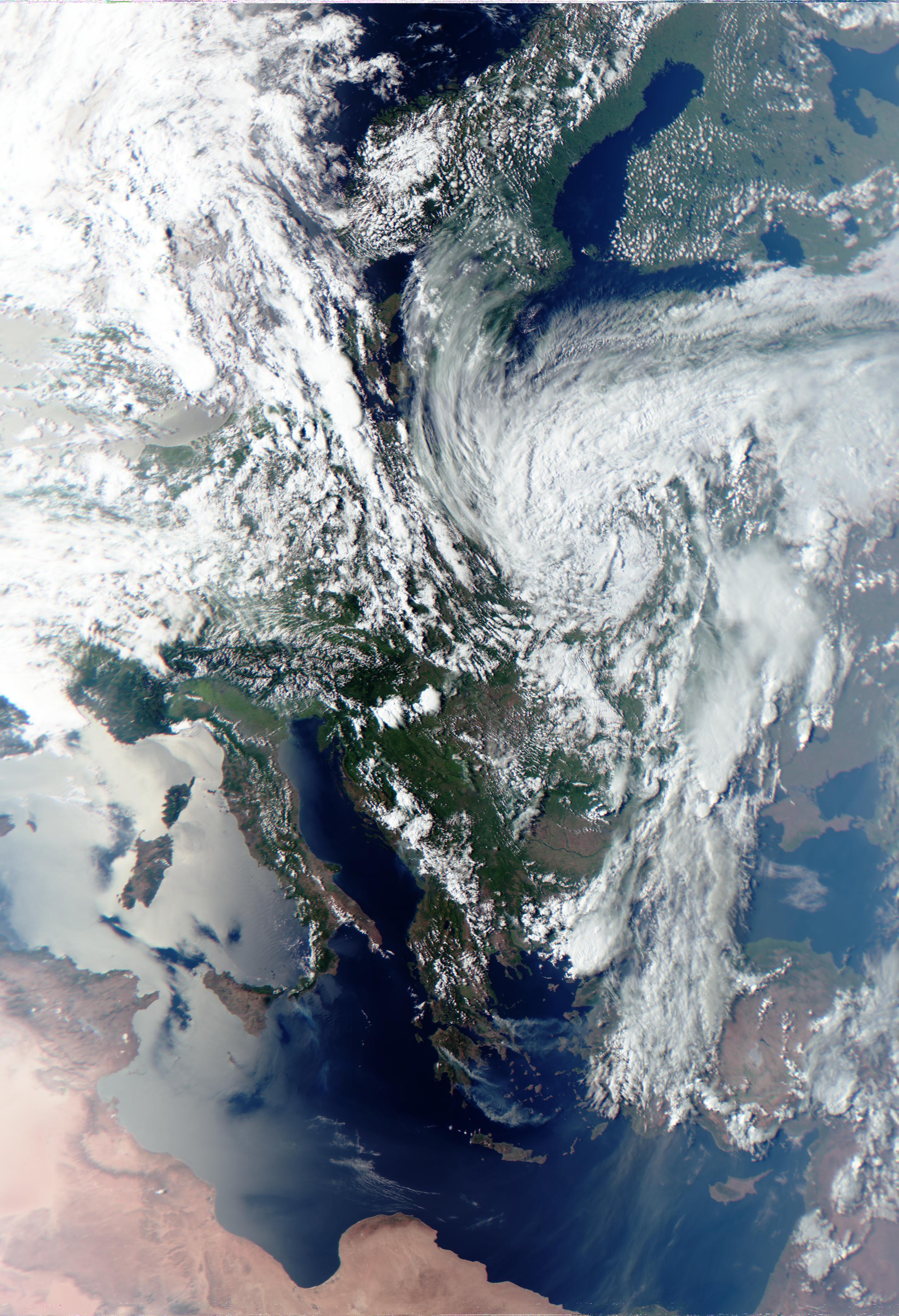
Following are direct links to image examples of HRPT decoded from all four satellite types (not embedding images here directly to preserve vertical space);
Note that the colors differ for each one as each satellite type offers a different spectral band selection. All besides FengYun-3 are false color composites utilizing mostly infrared light, while the FengYun-3 composite is a natural color mix of visible red, green and blue bands with the same IR bands as the other satellites. Also note that the image quality is decreased in these examples, partly due to my own poor antenna tracking but mostly because the images are jpegs. Unlike LRPT, HRPT is not compressed at all, and to demonstrate here is a lossless png crop from the above NOAA image (also without geometry correction to further reduce blur).
⇈ Table of contents
↓ 2.1 Computer
⇊ 3. Tracking
⇈ Table of contents
↓ 2.2 Receiver
Because the HRPT antenna needs to be in a wide open area with a good view of the sky, connecting it to a computer may be a challenge. I strongly recommend using a laptop, the actual hardware requirements of which aren't very strict as to this day I am successfully using an HP630 with a dual-core 1.5 GHz Intel Celeron. Nowadays this laptop would go for around 30 - 40 € and it is still fast enough for 6 MHz baseband recording (not a MHz higher than that though). I did however replace its hard-drive with a cheap SSD, since fast write speed is required.
It is important to have the laptop as far from the antenna as possible. I usually mount the SDR on the arm of my dish and then connect it to the laptop using a 5m USB 2.0 active extension cable. When selecting a cable like that, it is important to make sure that it's rated for full-speed USB 2.0.
⇈ Table of contents
↓ 2.3 Amplifier
The minimum requirements for an SDR receiver are that it has to be able to tune up to 1.7 GHz and sample 2.6 MHz of spectrum. This will cover the POES, Meteor-M and MetOp setellites, while at least 3 MHz are needed for FengYun-3. The RTL-SDR V3 and other receivers based on the same hardware (such as the Nooelec NESDR SMArt v4) will have no trouble recording and decoding POES and Meteor-M, while also being able to decode MetOp HRPT using the 2.56 Msps mode, although with reduced performance (expect images to be slightly shorter than those received by higher rate SDRs). While their ADC can sample at higher rates, it is usually not stable enough to actually record and decode anything, so they aren't usable for FengYun-3 HRPT. However, as FengYun-3C is now the only remaining satellite of that series, and with a strict geographical restriction, it is possible to get pretty much the full experience of HRPT decoding with just and RTL-SDR or an equivalent.
As such, the receiver I would recommend for a starter setup would be either the RTL-SDR V3 or the NESDR SMArt v4, in fact there's a good chance you already have one of these laying around. Something more expensive and more capable like the Airspy Mini will deliver better performance with the two MetOp satellites and enable reception of the one remaining FengYun-3 satellite, but it is up to you whether such an investment is worth an arguably marginal improvement.
Another important characteristic of the SDR is what kind of Bias-Tee it has, if any, as that will also play into the following section. The RTL-SDR V3 comes with a 4.5V/180mA software-controlled bias, while Nooelec sells a variant of the NESDR with a permanently enabled 4.5/250mA bias. The Airspy Mini has a software-controlled 4.5V/50mA bias, which is on the weaker side.
⇈ Table of contents
↓ 2.4 Dish Reflector
Due to the high microwave frequencies that HRPT is found at, it is pretty much mandatory to use at least a low-noise amplifier (LNA) between the antenna and the SDR. The LNA needs to be connected as close to the antenna as possible (ideally directly to it), so that it can quickly amplify the very weak 1.7 GHz signals collected by your dish reflector before they have time to dissipate inside the coax and RF circuitry of the SDR. While it is possible to detect the HRPT signals with an SDR connected directly to the antenna without an LNA, once it is added it improves the reception so significantly that there really isn't a point trying to get a good HRPT decode without one.
While a wide-band LNA such as the LNA4ALL or the SPF5189z works just fine on 1.7 GHz, due to its wide-band nature it can often result in very strong interference from the lower bands (especially broadcast FM) completely overwhelming the weak and delicate HRPT signal. This is why a filtered LNA is usually used for all kinds of microwave reception.
The ones that you will see used most commonly (and ones I recommend as well) are the Sawbird amplifiers from Nooelec. These come in many variants, but for HRPT only the "GOES" variant is relevant. The Nooelec Sawbird GOES is a low-noise amplifier with an integrated 1650 - 1720 MHz bandpass filter. It itself comes in two variants, the normal "Sawbird GOES" and the "Sawbird+ GOES". Both operate in a 3.5 - 5.5v range, with the normal variant drawing 30mA and the "plus" drawing 180mA while also offering higher amplification. For HRPT reception you usually won't be using very long runs of coaxial cable, so I would recommend the standard cheaper lower gain variant, as its lower current draw also puts less stress on the SDR and the USB port when powered using Bias-Tee.
Speaking of which, when using an SDR setup with a powered LNA in the chain, no matter whether it's the Sawbird or something else, it is important to make sure that no current gets where it's not supposed to. Normally a short circuit on the coaxial cable only disrupts the received signal, but when Bias-Tee power is used it has a potential of damaging the SDR. On the other hand, when external power is used for the LNA, measures need to be taken to prevent current flowing from the LNA into the SDR. Some LNAs (such as the common SPF5189z boards) have DC-isolated RF connectors so this isn't an issue, but something like the Sawbird has been proven to leak current into the RF output port and into the SDR, meaning that a separate DC block has to be added on the input of the SDR. Consider this whole paragraph a disclaimer; always double-check your connections and refer to a datasheet of your SDR and LNA to make sure whatever setup you are using won't be damaged.
⇈ Table of contents
↓ 2.5 Dish feed
The dish reflector is the core part of a HRPT setup, as that directly dictates how strong the received signal is and how difficult it is to track the satellite. A larger diameter will provide higher gain but also a narrower beam. In turn, a narrower beam makes it more difficult to track the satellite, but it also has better selectivity and potentially lowers the amount of unwanted signals being received. The dish size recommended by official HRPT documentation is up to 2 meters, however for amateur use a typical 70 - 80cm offset dish is perfectly usable.
Depending on where you live there may be different types of dishes readily available, often cheap or outright free from people transitioning from satellite TV to cable or terrestrial FTA. Typical European "Astra/Eutelsat" offset dishes usually come in a 60 - 80 cm diameter range. The United Kingdom specifically seems to be using mesh dishes for TV reception a lot, which is a good way to reduce wind loading. A quick Google search reveals that DirecTV "Slimline" dishes can be up to 32 inches (81cm) wide, but much larger prime focus dishes (often for the C-Band) can be available for cheap or free in the Americas, Africa, or Asia (pretty much anywhere other than Europe).
You may also be familiar with WiFi grid reflector dish antennas that are often reused for HRIT reception, which happens to be in the same frequency range as HRPT. And indeed such an antenna would also be usable for HRPT, provided that it is big enough. The grids are often elliptical or rectangle-shaped, so to match the gain of an 80cm offset dish you would need something like a 100cm wide grid. I personally would go with a smaller dish rather than a larger grid, although the grids do provide lower wind loading and already come with a feed that can be easily modified to work around 1.7 GHz (same way as its done for HRIT reception), or in some cases the 2.4 GHz WiFi feed may work without mods. Do keep in mind though that the stock grid dish feeds are linearly polarized, which will result in lower gain when used for HRPT reception (not an issue with HRIT which is also linear). More details in the next section;
⇈ Table of contents
↓ 2.5.1 Reflector
⇊ 2.6 Example Setup
The dish reflector itself is only a half of the antenna. It only concentrates the radio waves broadcast by the satellite; to collect and actually use them we need a more "conventional" directional antenna placed at the focal point of the dish (called the "feed"). Chances of you obtaining a dish that already has a feed that works well for the HRPT frequencies are pretty low though - in most cases the dish will be equipped with an LNB for satellite TV reception, which, depending on the band, contains an integrated feed for much higher frequencies (5 - 12 GHz). To use a dish like that for 1.7 GHz HRPT, we will have to get rid of the LNB and equip it with a custom feed (don't throw the LNB away though, as there are other radio projects it could be used for).
As mentioned, the feed of a satellite dish is essentially just a directional antenna. However we can't just use the highest gain antenna possible (which is something you would do in a "normal" case). Remember the dish is what does most of the signal collecting, so, to make full use of its surface area, the beam width of the feed antenna needs to reasonably "illuminate" it. A too narrow beam width results in the dish being "under-illuminated", meaning that the antenna isn't fully utilizing all of the signal the dish is collecting and focusing. A too wide beam on the other hand results in the dish being "over-illuminated". Not only is it then not utilizing the gain of the feed the most efficiently, but it also picks up reflected signals and noise coming from behind the dish. Because our dish is mostly aimed up (obviously...), an over-illuminating feed would be allowed to receive a lot of background noise coming off the ground. You can see this effect in action once you have your setup ready and working; aiming the dish at the ground will substantially raise the noise floor of your SDR.
In theory, a perfect feed for a dish would be one that has a beam width and shape matching the dish with a sharp cutoff at the edges and complete rejection of signals coming from outside the dish. This sadly isn't possible in the real world, but we can at least try to get as close to that scenario as possible. A good feed in practice will actually slightly under-illuminate the dish, sacrificing a small portion of the dish area near the edges (which is the least efficient anyway) in order to improve noise rejection. This is especially helpful with DIY feeds (such as the ones often used for HRPT) as we usually don't have a good way to measure its beam shape, so by purposefully under-illuminating we get a bit more error margin; losing a little bit of the signal collected by the dish is better than letting in signal-drowning noise and interference.
Knowing all this we can now move onto the selection of the appropriate feed type.
In the case of most LNBs the feed is a waveguide with a small quarter-wave monopole positioned at its bottom. A waveguide feed like that is very flexible when it comes to its beam width and polarization, however we have to remember that the size of the antenna grows together with the wavelength; a 1.7 GHz waveguide feed would be almost six times larger than a Ku-Band satellite TV LNB, also requiring some relatively precise metal work to get the shapes and dimensions needed. And (especially with prime focus dishes) having a very big feed in the way of the received radio signals would hurt the performance. One feed that is commonly used by radio amateurs receiving the linearly polarized HRIT from geostationary satellites is a cantenna, which is a kind of a compromise between the size and performance when compared to a proper waveguide feed with choke rings.
There is however another feed type, very commonly used for HRPT reception, that is just as (if not more) flexible, which is a helical feed. It is very easy and cheap to build, it is extremely forgiving when it comes to construction imprecision, and can be easily adapted for any desirable beam width. It also provides the necessary circular polarization and is relatively small.
The helical feed consists of only two wavelength-dependent parts; the reflector and helix itself. These can be as simple as a thin sheet of metal and solid-core copper wire.
⇈ Table of contents
↓ 2.5.2 Helix
The reflector should be at least the size of 3/4 of a wavelength. In case of 1.7 GHz that is around 13cm, meaning that a valid reflector can be a square with each side at least 13cm long, or a circle with at least 13cm diameter. For example, a 13cmx13cm square of sheet aluminium or copper will work just fine. Sheet iron can be used as well, as you can easily obtain that from old electrical appliances (like microwaves, computer cases, ...), although it can rust over time without additional protection.
⇈ Table of contents
↓ 2.5.3 Connector and Matching
The helix is a spiral of wire with a diameter of wavelength/Pi, or 56mm for 1.7 GHz. The number of turns and the spacing between them depends on the desired beam width of the helix. A helix should have at least 3 turns to even have the characteristics of a helix, with around 16 turns being the highest practical number, but the number of turns needed to feed a dish depends on the illumination angle of the particular dish as well as the chosen turn spacing.
The spacing for helical antennas is usually chosen to be around 0.21-0.28 wavelength, however I personally tend to use lower values, around 0.14wl for normal offset dish feeds. This calculator can be used to experiment with different spacings and turn numbers, with the "HPBW (Half Power Beam Width)" being your indication of what the expected beam angle of the helix would be. For common TV offset dishes this angle is around 75 - 80°, so I personally would use a 5.5 turn feed with 0.14wl spacing, that according to the calculator comes out to around 60°, which seems to work quite well (as mentioned above, some under-illumination and margin is desired). If you have a prime focus or some other non-standard dish, you can work out the illumination angle with simple trigonometry by measuring the diameter of the dish and the distance between the end of the feed arm and the center of the dish.
Another very important characteristic of a helical antenna/feed is its polarization. You may have already realized that there are two ways to wind the helix; clockwise or counter-clockwise, and indeed the way the helix is wound dictates its polarization. HRPT signals are right-hand circularly polarized (RHCP), however this polarization is inverted when reflected by a dish which means our receiving helix needs to be left-hand circularly polarized (LHCP). You can determine the polarization of a helix by looking at its very first turn just above where the reflector would be. If the conductor goes up in a clockwise manner, then the helix is LHCP, if counter-clockwise then RHCP. If that is hard to imagine (which it is for me), you can simply look at the photos of the feeds that you will find below (all are LHCP).
My recommended concrete dimensions for a HRPT helical feed for a standard offset dish would therefore be;
Consider these just very rough guidelines though. As mentioned, the helix is a very forgiving antenna, and because we are only using it for reception and not transmission its forgiveness is only exaggerated. You are encouraged to experiment with different characteristics (except polarization).
I will also mention that if you own or have access to a 3D printer you can print a plastic scaffold which will both hold the helix in place and also act as its support connecting it to the reflector. I have released a set of helical antenna scaffolds on Thingiverse, including the 5.5 turn HRPT one, which you can find here. Of course 3D printed support isn't required, by all means you can use any other non-conductive material, such as a strip of hard plastic with pre-drilled holes or a plastic pipe with the helical conductor attached to it in some other way. You can see examples of different real-world solutions on the following photos;

⇈ Table of contents
↓ 2.5.4 Mounting
Once you have both the helix and the reflector ready, you will have to attach them together using a connector. The type of connector doesn't really matter as long as you can acquire the necessary adapters to connect it to the LNA and subsequently the SDR. Something like a "panel mount" female SMA connector would probably be the most ideal, as it only requires one hole to be drilled and can be connected to the rest of the setup through a male-male SMA adapter (which is cheap and even comes for free with the Nooelec Sawbird). The center pin of the connector is where the helical conductor is soldered, while the outer part has to make good electrical contact with the reflector (ground) plate. Below are two illustrations from the ARRL Antenna Book showing how the connector should be attached to the plate and helix while achieving a good impedance match;

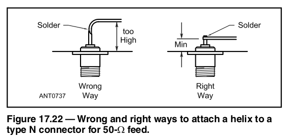
Note that in some cases a "matching strip" is also added to the first quarter turn of the helix, which is in the form of a curved copper plate soldered to the helix conductor and running parallel to the reflector. This is to further decrease the impedance of the helix to bring it closer to 50 ohms. I personally don't include a matching strip in helical feeds, as they are only used for receiving and work "good enough" without it. But once again you are free to experiment. I found that just deforming a portion of the first turn so that it runs closely parallel to the reflector helps with impedance matching to some degree by itself (and in fact my mentioned 3D printable scaffolds already come with that feature).
I also put the connectors on my feeds in the center of the helix and reflector, with the first turn of the helix conductor having an additional "L" shaped section at its end that joins it to the connector (not shown in my photo above as that is an older feed). Once again, in my case I found that adding this section and having it parallel to the reflector helps with matching, although it may result in different characteristics when used with a matching strip.
Basically, to reiterate, a receive-only helix is very forgiving in its construction, so you generally have a lot of freedom when it comes to the mounting and feeding configuration you use.
⇈ Table of contents
↓ 2.6 Example setup
After fully assembling the helical feed, you also have to come up with a way to mount it on the dish. In an ideal setup, the phase center of the helical feed should be aligned with the focal point of the dish. You can easily locate this point by looking at where the entrance of the LNB waveguide would be placed. That point should roughly overlap with the center of the first turn of the helix. Note that on 1.7 GHz the focal point alignment doesn't require that much precision. This is especially helpful because the reflector of a helical feed will usually not fit on the dish arm perfectly (as denoted by the red marks on the following illustrations), so it will need to be offset slightly above it in many cases (as seen in the next section). The following image also shows three examples of offset dishes with different feed arm shapes - while all of them can be used for HRPT just fine, the first one is the least suited to hold the helical feed while the last one has the most clearance to fit the reflector.

⇈ Table of contents
↓ 3. Tracking
Overall there isn't one "good" way to mount the feed, and I haven't even touched on how and where to mount the dish itself so that it can freely spin around in both azimuth and elevation axes, as there simply are way too many possibilities to cover. So I figured the best thing I could do would be presenting some already existing and working setups for HRPT reception.

On the above image you can see what my setup for receiving HRPT (and all kinds of LEO satellites in general) looks like. There are a few things to point out;
As was noted in the previous sections, the HRPT feed reflector is way too big to fit properly into the LNB holder, so I have it placed there with a slight offset, meaning the helix is actually slightly above the original focal point (or below when its upside down?). This doesn't matter too much, as the dish essentially acts like a mirror so offsetting the feed a little outside of the original LNB focal point will be compensated for simply by changing the pointing angle of the dish (which you will do seamlessly and without even noticing while tracking by hand). This is also why satellite TV dishes can receive multiple satellites at once from different positions using multiple LNBs next to each other.
Another notable thing about my setup is that the dish is upside down when tracking a satellite. This loosely follows on the idea of the dish acting as a "mirror". When placed right-side up, an offset dish by itself has to actually aim below the target satellite. While this usually isn't a problem with geostationary satellites that are constantly at a high elevation, a low-Earth orbiting satellite will spend a lot of its time at very low elevations when passing over you. A TV dish with an offset angle of around 20° for example would have to always aim 20° below the satellite. This would cause issues when the satellite itself is lower than 20° above the horizon, as the dish would not be able to aim low enough (due to the lower part of the dish hitting its tripod mount). A very simple yet effective solution to this problem is to just flip the entire dish upside down; now the satellite will never be outside the elevation range (provided that the dish itself can freely aim through the full 180° elevation axis, as during very high elevation passes it will briefly flip right-side up again).

Which brings me to the third notable point about my setup; how the dish can freely spin on its axes. You can see how I solved the elevation axis on the rightmost image. I removed the original mounting clamp of the dish and ran a long threaded rod through the remaining mounting profiles on the backside of the dish and a hole that I drilled into the very tip of the tripod (it is an aluminium tripod intended for camping satellite dishes). To make sure the dish won't slide from side to side I also 3D printed two spacers and put them between the tripod and the dish clamp. If 3D printing isn't an option, something like a drilled/hollowed out wooden broom handle or a cut pipe would also do the job.
The azimuth axis solution isn't clearly visible on the images, but basically I've just drilled another hole in the tripod right above its own clamp used to secure the telescoping boom. Then I put another bolt through it so that I can leave the clamp unlocked, which results in the boom being able to freely spin around while slightly extended without sliding back inside the tripod. I also printed a plastic "washer" that is between the securing bolt and the locking clamp to prevent the bolt from scraping it too much while rotating (also not visible on the photos).
In my setup I mount the SDR (Airspy Mini in an additional metal case) on the arm right by the feed, only using a short piece of coax to connect the SDR to the Sawbird LNA which in turn is directly connected to the feed, minimizing the losses in the RF paths. The SDR is then connected to a laptop with a 5m USB 2.0 active extension cable. Nowadays I have the SDR secured to the arm with 3D printed brackets and bolts, however up until very recently I simply tied it to it with some garden wire. It is important to make sure the USB connections are secure though, as if they disconnect while receiving it will result in a very annoying and long signal interruption.
I also have an additional set of photos of an example HRPT setup, this time based on the previously mentioned grid antenna. These have been kindly contributed by Victor Boesen.

You can see the that the reflector of the linear feed has been flipped around, this is done to improve the performance around 1.7 GHz as the feed has originally been designed to operate at 2.4 GHz WiFi frequencies. It is however possible to get grids like these with actual 1.7 - 1.8 GHz feeds (intended for cellular networking I think), although they seem to be more rare. Nooelec used to sell a purpose-built 1.7 GHz grid antenna on their website in a kit form for HRIT reception, also including a Sawbird GOES and an NESDR SMArt XTR receiver, although I would advise against this, as the price is substantially higher than what you would pay even for a much larger used offset dish reflector, and the SMArt XTR SDR also doesn't have a very good price/performance ratio.
Keep in mind though that a grid antenna like this with a linear feed will suffer from a slight polarization mismatch loss (around 3dB for a linear/RHCP mismatch), although the generally better construction and matching will make up for the loss to some extent. Whatever the real loss is, it doesn't seem to be too bad (with a big enough reflector) as Victor has proven.
⇈ Table of contents
↓ 3.1 Tracking software
⇊ 4. Decoding
Prediction and tracking of the HRPT satellites is probably the most significant difference when compared to receiving VHF or UHF satellites. As has been thoroughly described already, the wide and relatively weak HRPT broadcasts absolutely require a tracked, high-gain, directional antenna if any good results are to be expected.
The hand-tracking technique is something you will have to develop on your own, so that it suits you best. I usually use a tracking app to get the rough idea of where the satellite is, and then I simply watch the signal in real time. I found that it is important to not do very sudden moves when it looks like the signal level is dropping, as it is better to have a few seconds of lower quality signal rather than no signal at all.
Some satellites can also be very confusing to track manually using the signal level; the antenna that the Meteor-M satellites use seems to have a lower gain directly below it, meaning that during a high elevation pass you will probably observe the strongest HRPT signal at around 20-50 degrees, with the level actually decreasing as the satellite gets overhead.
NOAA-15 also seems to have many nulls in the radiation pattern of its HRPT antenna - in many cases when I was trying to track this satellite it would happen that the signal level dropped basically to zero even when there was no obstruction between my antenna and the satellite. Although this probably won't bother you too much as NOAA-15's HRPT is very weak overall and not very desirable for reception with a small dish.
Hand-tracking fast-moving space satellites with a very high gain antenna is a skill that will take some time and practice to develop, and it is something that I have yet to master myself (as evident on the example images). You will most likely end up with rather bad results on your first couple tries, but it is important to not be discouraged. For example if you make a tracking mistake in an otherwise good pass don't just quit tracking, even if the resulting image quality will be poor you can still use the rest of the pass to practice your tracking so that it won't be as likely to happen next time.
⇈ Table of contents
↓ 3.2 HRPT Frequencies
Prediction of the passes is the same as you may already be used to with APT, LRPT, or ham radio satellites. It is however important to note that some satellite tracking apps may not include the full HRPT fleet by default as it simply isn't what people usually want to track. This is why I recommend using software that lets you define your own TLE sources. For Windows, Linux, and MacOS I would suggest using gpredict, but I also find it much more convenient to have the tracking info on a separate screen on my smartphone instead (depends on personal preference), so for Android I recommend using Look4sat (with all the "fancy" features such as the radar screen effect and compass disabled). Sadly I myself can't give any advice on app selection for iOS because I'm way too poor for that.
Just a note on Look4sat though - it downloads satellite frequency information from the SatNOGS database. In my own experience I have found this information to not be very reliable, which understandably isn't a fault of SatNOGS as the satellites that I mostly focus on aren't something any SatNOGS receivers would be particularly interested in. My point is that you should always make sure you have correct and up-to-date frequency information, although none of the currently active HRPT satellites are really expected to change their frequency.
⇈ Table of contents
↓ 4. Decoding
As of November 13, 2022, the frequencies used for HRPT dissemination by the currently active satellites are;
⇈ Table of contents
↓ 4.1 Recording
⇊ 5. Conclusion
There are four main "stages" that I would divide the decoding process into;
Depending on the software of choice the process and results will differ.
⇈ Table of contents
↓ 4.2 Decoding
Today's HRPT software offers the ability to demodulate the signal directly as it comes off the SDR, meaning that this step can be skipped. This is what's commonly referred to as the "realtime" decoding method. However, I strongly suggest you start off with the "offline" method. This involves first recording the HRPT signal using appropriate software. A few examples include;
I personally use SDR# for the vast majority of signal recording with my Airspy Mini, RTL-SDR V3 and HackRF. In my opinion it has the best GUI for baseband recording and playback as well as general signal monitoring. It does however need a baseband recording plugin and some configuring done before it can be used to record HRPT, although I think the latest versions come with the plugin pre-packaged, and if not then the community plugin package can be downloaded (and the unneeded plugins stripped).
SDR++ is a good open-source alternative of SDR#. It also uses soapy-sdr which means it supports more devices than SDR#. I used it on both Linux and Windows for HRPT recording successfully, but I did return to SDR# on Windows in the end. SDR++ however is still in early stages of development (when compared to SDR#) so I expect it to only get better. Definitely the best choice for Linux already though.
November 2022 update: At this point I think I would almost recommend starting with SDR++ even on Windows. I still use SDR#, but at this point it's mostly because I already got used to it and it still has a superior recording player plugin (which however plays no role in HRPT or other satellite reception in general). If you are new to SDR, it may be better for you to just get used to the open-source SDR++ from the very beginning.
When receiving (and recording) any signal for demodulation, it is ideal to sample at least twice the signals own rate (not to be confused with the actual signal bandwidth). For example, MetOp HRPT is being broadcast at 2.33 Msps, so for the best possible result at least 4.66 Msps rate should be used by the SDR. This ratio is often called "sps", or "samples per symbol", as it describes how many samples the receiver captures in the time it takes the received digital signal to transmit one symbol (1 bit with BPSK, 2 bits with QPSK, ...). As described above, 2 sps are needed for an ideal decode, however some demodulation techniques can theoretically work with just 1 sps, but in practice slightly more than that is needed.
This is important for us because that is how the RTL-SDR V3 can record and decode MetOp HRPT broadcasts. It has been briefly mentioned at the beginning of this guide that the RTL-SDR V3 is only stable up to 2.56 Msps. When used with 2.33 Msps MetOp HRPT we end up with roughly 1.1 sps, which is at the very edge of the demodulation capability, but in my own test I was able to successfully decode a MetOp HRPT signal recorded with the RTL-SDR V3 running at 2.56 Msps. I imagine the MetOp HRPT error correction helps a lot in this low margin case.
Following are the different signal rates of HRPT and the recommended SDR sampling mode for the RTL-SDR V3 (and alternatives) and the Airspy Mini (all rates are in Msps);
| HRPT type | Symbol rate | Ideal sampling rate | RTL-SDR V3 rate | Airspy Mini rate |
|---|---|---|---|---|
| NOAA/POES | ~0.665 | ~2.5* | 2.56 | 3 |
| Meteor-M | ~0.665 | ~2.5* | 2.56 | 3 |
| MetOp | ~2.333 | 4.7 | 2.56 | 6 |
| FengYun-3 | ~2.8 | 5.6 | - | 6 |
*POES and Meteor-M use a different modulation method that consists of two signal sidebands with a carrier in the middle; even though the symbol rate is relatively low, at least roughly 2.5 MHz of spectrum need to be sampled to capture the signal ideally
Once you are done recording the signal using software of your choice, you will be left with a .wav file (or .raw in "special" cases) which contains the baseband data for demodulating.
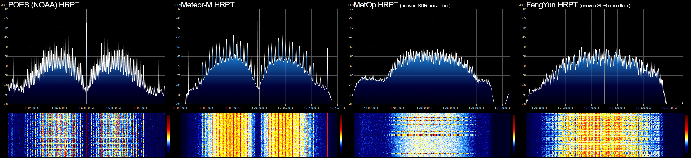
Also following are screenshots of the SDR# FFT display showing the HRPT signals received from each satellite type;
⇈ Table of contents
↓ 4.3 Post-processing
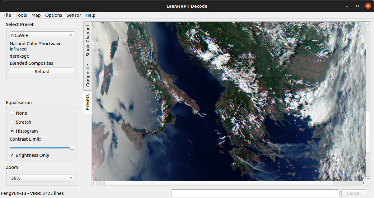
For HRPT reception and decoding, I use LeanHRPT-Demod and LeanHRPT-Decode. Both are open source and run on both Windows and Linux.
LeanHRPT is divided into two separate apps; Demod and Decode that each do exactly what it sounds like. Demod is used to demodulate the signal from the radio broadcast into either raw or minially processed binary data, and Decode further processes this data into an image.
⇈ Table of contents
↓ 5. Conclusion
LeanHRPT-Decode also allows for many different ways to post-process the HRPT image data, from color compositing, to geometry correction, geographical projection, white balance, equalization, and so on.
All of the HRPT image examples in section 1.4 are files directly exported from LeanHRPT-Decode.
To learn how to use LeanHRPT-Decode, see the wiki.
⇈ Table of contents
↓ 5.2 Future of HRPT
While this guide has mainly been focused on a "minimalist" beginner setup, there are many ways it could be improved upon to get better and more consistent results (all of course requiring additional effort and investment).
One of the biggest improvements you can make to your setup is to use a motorized tracker. Of course this is only possible in specific cases, for example if you live in an apartment or just a crowded area you may have to carry your entire setup somewhere else to receive the satellites, in which case a rotator would make the setup much more bulky and would probably be redundant (you already have to be present so why not do the tracking yourself). There is of course also the fact that even the "cheap" rotators can go upwards of 1000 EUR, which is a huge investment for a hobby. I personally do all my tracking by hand and don't foresee myself getting a rotator for quite some time, as even if I could afford one I would still need to sort out a lot of other things, such as somehow running power and internet connections to the yard and getting and housing a dedicated computer outside.
Another, more affordable improvement that could be made would be focusing on the feed. Even a helical feed as described here could have its performance improved when tuned properly using a VNA. While you can just build one "blind" using the dimensions I've provided, it will never be perfectly tuned to 1.7 GHz as there are simply way too many factors that affect its response. I've bought the NanoVNA V2 a while back that I use to fine tune my helical feeds for a slight performance boost.
It is also possible to buy already pre-made HRPT feeds. For example rfhamdesign sells dish feeds for the 1.4 - 1.8 GHz range for 121 EUR, which admittedly is still pretty expensive as you can probably put together the full HRPT setup as described by this guide for a lower price than that. There is also the Russian Antex company that sells a 1.7 GHz patch feed for offset dishes for 2500 RUB (around 30 EUR), which is a really great price but they don't seem to ship outside of Russia.
Full disclaimer though; I have not bought and do not plan on buying any of the pre-made feeds as I don't think any performance improvement would be worth the price increase over a DIY helical feed. What does however have the biggest impact on the performance of the setup is the dish diameter;
Increasing the dish diameter is the most obvious and straight-forward improvement you can do. There isn't much more I can say that already hasn't been said - a bigger dish will give you better signal but will also make the setup bulkier and add tracking difficulty.
One last thing that comes to mind would be experimenting with a differently shaped reflector of the helical feed. It may be possible to use a conical or an otherwise shaped reflector to decrease the amount of noise and interference picked up by the helix, this is something I want to experiment with in the future so stay tuned for updates. This could have the effect of increasing the signal-to-noise ratio not by increasing the signal, but instead by reducing the noise.
⇈ Table of contents
↓ 5.3 Beyond 1.7 GHz
While HRPT is a big step-up in quality, resolution and number of available satellites when compared to APT and LRPT, the fact of the matter is that even HRPT is already being phased out.
NOAA-19 was the last NOAA satellite to carry HRPT. There have been some plans to include "LRD" on future NOAA satellites, which would essentially be even higher rate HRPT broadcast in the 1.7 GHz band, however NOAA did confirm that the NOAA-21 satellite will not include this service and it is safe to assume that neither will any other future American satellites.
MetOp too has completely dropped HRPT, with the upcoming MetOp-SG constellation not planned to broadcast anything on 1.7 GHz. The same goes for FengYun-3, with the 3A, 3B, and 3C satellites being the only ones with confirmed 1.7 GHz HRPT payloads. Some documentation available online does mention the inclusion of L-band HRPT on later satellites, however neither FengYun-3D or 3E seem to have done so (and in fact some documents state that not even 3B and 3C should have had HRPT to begin with, so it's anyone's guess).
The Meteor-M constellation is the only one with scheduled future launches that have a high probability of including not only HRPT but also LRPT. But just like most other Russian satellites, Meteor-M launches have been plagued with complications and delays, with Meteor-M N2-3 currently being planned for a launch not earlier than December 2022.
⇈ Table of contents
↓ 5.4 Actual conclusion
Even though the number of active HRPT satellites is only set to decrease as time goes by, direct reception of weather satellite imagery still hasn't been cancelled fully. All of the HRPT satellites have instead transitioned their broadcasts into the X-band - a part of the radio spectrum in the 7 - 10 GHz range.
Not only can you encounter modern "HRPT equivalents" in the X-Band on the NOAA, MetOp, Meteor-M and FengYun-3 satellites, there are also many other spacecraft broadcasting their data that never had 1.7 GHz payloads in the first place, such as Terra, Aqua, or OceanSat-2, with many others planned to be launched in the future.
But if you think that spending 121 EUR on just a HRPT feed is way too much then there probably is no point even considering direct X-band reception, as every single element of a functional X-band setup will cost you significantly more than you would spend on an entire L-Band HRPT setup.
I myself would like to experiment with X-band reception at some point, but just like getting a rotator it is something way outside my budget.
While I hoped to make this guide much more detailed and specific, I decided to cut a few corners and leave some things more open-ended as you may have noticed. That is because I've already tried making a much more in-depth write-up before, however I was never able to finish it due to it getting way too convoluted and outright confusing, but I hope this was still helpful to you in some ways.
I thank you for your time and (presumably) reading this guide. If you did find it helpful, I would very much appreciate if you shared it, as there seems to be a lot of general misunderstanding of HRPT and its "complexity".
As always if you have some suggestions or questions related to this blog post, feel free to contact me via my social media linked in the main page.